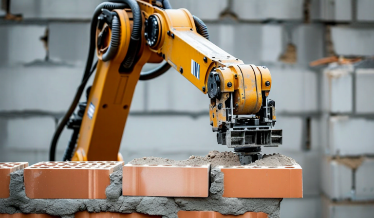
The popular image of a bricklaying robot is a robotic arm picking up bricks and setting them in mortar. The actual engineering problem is far more difficult than that image suggests. Mortar is a rheological fluid with variable consistency. Bricks have dimensional tolerances of plus or minus 5mm from the manufacturer. Construction sites are uneven, dusty, and subject to thermal expansion that shifts reference points throughout the day. Any robotic masonry system that works reliably in the field has solved a set of non-trivial mechanical and computational problems that are worth understanding.
The Mortar Deposition Problem
Conventional mortar mix - Type S or Type N portland cement mortar - has a working time of 60 to 90 minutes at ambient temperatures between 50 and 90 degrees Fahrenheit. Below 40 degrees, it sets slower and its final compressive strength is compromised. Above 95 degrees, it can set in under 30 minutes, creating a situation where mortar deposited at the start of a course has begun to cure before the brick at the end of the course is placed. A skilled mason manages this by adjusting mix water content throughout the day - an act of constant empirical judgment that robots cannot replicate by simply following a recipe.
Terran's masonry end-effector addresses this with a temperature and humidity sensor array at the mortar nozzle, combined with an adjustable water injection system. The controller samples ambient conditions every 90 seconds and adjusts the mortar slump - a measure of consistency similar to concrete slump - to maintain a target workability range. The mortar pump system draws from a sealed hopper that slows evaporation, extending effective working time by 25 to 40 minutes compared to an open mortar board. This is not a glamorous innovation, but it is why the system works in Phoenix summers rather than only in controlled laboratory conditions.
Positional Accuracy and Drift Correction
A brick wall requires horizontal course alignment within 3mm over a 10-foot run to meet typical building code requirements. Achieving that with a robot arm mounted on a mobile platform requires solving a position accuracy problem across three coordinate axes simultaneously. The mobile base positioning, the arm extension, and the wrist orientation all contribute independent sources of error that stack if not actively managed.
Standard industrial robot arms achieve positional repeatability of 0.1 to 0.5mm in fixed-mount configurations. A robot arm on a mobile platform that has rolled across a construction site on ground that deviates from level by 15 to 20mm starts each placement cycle from a position that may differ from the planned position by several millimeters. Naive kinematics would accumulate these errors into visible course misalignment.

The solution is continuous reference correction. The Terran masonry system uses a combination of a fixed laser datum line established at job start and a visual odometry system on the end-effector camera. Before each brick placement, the controller runs a 200-millisecond verification pass that checks the end-effector position against both the datum line and the previously placed course. If the deviation exceeds 1.5mm, it adjusts the wrist orientation and arm extension before completing the placement. This adds roughly 0.8 seconds per brick to the cycle time but keeps cumulative error within the 3mm tolerance over 50-foot wall runs.
Brick Variability and Rejection Logic
Bricks from even a single manufacturer production run can vary in length by up to 5mm and height by up to 3mm. In hand-laid masonry, the mason adjusts mortar bed thickness to absorb these variations while maintaining consistent course height. A robot following a fixed mortar deposition program would produce walls where course height varies with the brick rather than with the design.
The system handles this through dimensional scanning before each placement. A structured light scanner at the pick position measures each brick in approximately 0.4 seconds. Bricks outside a 4mm dimensional tolerance window are flagged for rejection and diverted to a rejection bin. The controller adjusts the mortar bed thickness specification for bricks within tolerance based on the actual measured height, maintaining the target course height regardless of brick variation.
The rejection rate in field conditions runs between 2 and 6% of bricks processed, which aligns with typical quality-sorted brick manufacturer data. The system generates a per-pallet defect log that can be sent to the supplier for quality claims - a data artifact that manual masonry operations never produced.
Corner and Opening Handling
Straight wall runs are the easiest case. Corners require coordinating two arm orientations and managing the head joint at the corner accurately. Window and door rough openings require precise placement of end bricks and the transition from running bond to header courses. These geometric transitions are where most robotic masonry systems in the market either fail outright or require human operator intervention.
Terran's approach separates the problem into path planning and execution. The BIM import step, which happens before any robot is deployed to site, pre-classifies every brick position in the design as a standard field unit, corner unit, or special unit. The path planner generates a sequence that handles the arm configuration changes for corners as explicit programmed transitions rather than relying on the controller to figure them out at runtime. This front-loaded planning step adds two to four hours of pre-deployment engineering time but eliminates the majority of runtime exceptions in corner and opening handling.
Throughput vs. Quality Tradeoffs
Industry press often emphasizes the headline brick-per-hour figure for robotic masonry. That number is real but context-dependent in ways that matter. At maximum throughput - approximately 350 bricks per hour on straight field courses - the system is laying brick as fast as it can pick, orient, and place without running the full dimensional scan and position verification sequence. This mode is appropriate for interior CMU block walls where dimensional requirements are less strict.
For exterior face brick where visual quality and dimensional consistency are paramount, the full verification sequence runs, bringing throughput down to 200 to 240 bricks per hour. That is still faster than a skilled mason's sustained rate of 350 to 400 bricks per day (roughly 44 to 50 per hour in 8 hours), and it is achieved with more consistent quality than even an experienced mason can maintain across a full shift. The comparison is not 350 bricks per hour versus 50 bricks per hour - it is 240 bricks per hour of verified, documented placement versus 400 bricks per hour of undocumented manual placement. In the context of building systems that must satisfy structural engineer inspection, the documentation advantage changes the calculus.
What the System Still Cannot Do
Decorative masonry - corbeling, soldier courses, arches, and custom bond patterns - currently requires manual intervention or additional robot programming that is project-specific and expensive. The system is optimized for running bond, stacked bond, and standard flemish bond patterns, which represent the large majority of residential and multifamily masonry volume. Architectural masonry with complex geometric requirements remains in the human domain.
Similarly, repair and tuckpointing work on existing structures is not a current capability. The system is designed for new construction on prepared footings and courses, not for integrating with existing masonry of unknown dimensional history. These are tractable engineering problems, but they are not yet solved in a deployable product.
Why This Matters for Housing Costs
Masonry labor represents 18 to 24% of total construction cost for projects where brick or CMU is the primary structural or veneer system. A system that reduces the masonry labor requirement by 60 to 70% while maintaining or improving quality has a direct impact on project feasibility in markets where masonry is specified. As we discussed in our article on how robotics addresses the housing crisis, labor cost reduction at the trade level is where the supply economics actually shift.
The engineering described here is not final. Each field deployment generates data that feeds back into the control system calibration and the path planning algorithms. The system running today is meaningfully better than the system running 18 months ago, and the system running 18 months from now will be better still. That iterative improvement loop - field data driving engineering changes driving field performance - is the actual product development model for robotic construction systems.
Interested in the Technical Details?
Our engineering team presents quarterly technical webinars on robotic masonry and framing systems. Contact us for the next session.
Get In Touch